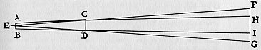
"When there are no glasses in the tube, the rays proceed to the object FG along the straight lines ECF and EDG, but with the glasses put in they proceed along the refracted lines ECH and EDI. They are indeed squeezed together and where before, free, they were directed to the object FG, now they only grasp the part HI" Galileo, Sidereus Nuncius tr. Albert Van Helden, pp. 38-39.
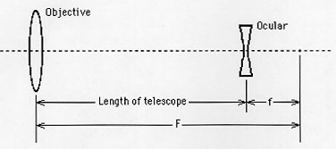
Actually, Galileo could not explain how his telescope magnified precisely. He did not understand, as we now know, that the magnification of his telescope can be computed by F/f (see top figure). Increasing the magnification requires lengthening the telescope. Our 10X telescope is about 4 feet long.
From the above picture, you can see that an image, HI, will be viewed upright, making the Galilean telescope useful for terrestrial purposes as well as astronomical. Keplerian telescopes, in contrast, invert the image.
Increasing the magnification on the Galilean telescope, like all telescopes, reduces the field of view. Perhaps Galileo built a 30X telescope, but it is doubtful that he used much in his observations. The field of view must have been very tiny.
The basic premise of the telescope tube is to align two lenses the appropriate distance from each other. For this telescope, the lenses are a concave convex (one side curved out and the other curved in) and a plano concave (one flat side and one side curved in). The plano concave lens is used as the "eyepiece" with the plano (flat) side facing the eye. The concave convex is used as the "objective lens" that is aligned with the eyepiece and with the convex side facing the sky. Notice that this lens is actually different than the plano convex lens used in the original Galilean telescope, but still gives the same results.
The following design uses pieces of the inner tube of the mailing tube to hold the lenses in place inside the outer tube. This is best illustrated in the following diagram, which shows the cross section of the telescope tube:
Take the short piece of the outer tube and cut or drill a hole (from 3/16" to 5/16" should be fine) directly in the center of the metal cap on the end. This will be the eyehole. It is important that this hole be as clean as possible (no metal protrusions) so that the the flat side of the eyepiece will fit snugly against the metal cap. An electrician's hole punch or Greenlee Punch works well for this task. If a drill is used, drill with a light pressure, then smooth out the inside surface as much as possible.
Place the eyepiece flush (flat side) against the inside of this eyehole. The large piece of the inner mailing tube left will be used to hold this in place. To do this, drill small holes around the outside of the eyepiece tube. Then, with the eyepiece properly in place, slide the inner tube into it, put glue into the holes, and turn the tube a little bit to spread the glue inside. Hold the tube snugly against the lens inside the cap until the glue dries.
Now, put this aside and take the large outer tube and the two spacers cut from the inner tube. Cut the closed end off of the outer tube, then use the other end to mount the objective lens (since that end already has a clean cut). Again, the "drill holes - put in glue" technique will be used to hold the spacers in place. First, check how far the inner spacer needs to be placed inside the tube so that the lens and other spacer will be able to sit inside the tube comfortably. Then drill holes in the outer tube around this area and glue in the spacer as before.
After the first spacer is in place and dry, place the concave side of the objective lens flush against it, and put the other spacer snugly against the lens to hold it in place (again using the drill - glue method).
Now there are two pieces, each containing one of the lenses. Slide the mailing tubes together as shown in the drawing above, and the telescope is done. By leaving these two pieces unglued, the telescope may be focused simply by sliding the eyepiece part inside the objective part. After a desired magnification/focus is found, the two pieces may be permanently attached (or some tape will give a semi-permanent attachment).
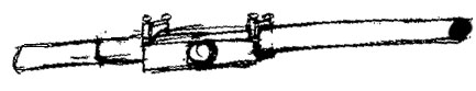
Two images of a finished tube are shown below. The first picture shows the telescope tube from the objective side while the second image shows the ocular end of the tube:

This image was produced by the star jumping in the field of view. We tried to have one person hold the telescope tube steady, but it takes very little movement to cause a star to move across the field of view when the field of view is only about 15 arc minutes. Moreover, our telescope would blow over often and required one person to hold it as still as possible, but this never really worked very well.
So, we built a new mounting and stars looked like this, with very little distortion.
The new mounting was constructed on a Saturday morning and afternoon, based on plans by Tom Williams. It looks like this:
This telescope mounting is composed of
Suggested Tools:
Instructions:
The base is constructed by attaching the plastic holder to a square piece of plywood and then adding four legs which extend outward. The big plastic tubing can be glued into the holder. At the top of the tubing, another plastic holder is put on, but not glued, so that the entire top of the mounting can be removed for adjustments and travel purposes. The top plastic holder is attached to a round piece of plywood which has a whole cut out of the middle and a screw inserted there. The support box will be attached here and can swivel 360 degrees.
The support box is constructed much like a shoe box except that one side is missing. The bottom has a rectangle cut out of end (see where Travis's hand is). This allows the bracket assembly to rotate all the way to a position perpendicular to the ground. Also, on the end of the box opposite Travis, cut out a semicircle to allow the telescope to rotate all the way to a position parallel to the ground.
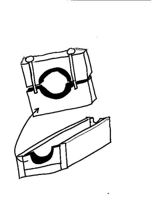
The bracket assembly encases the telescope. It looks like this:
It is made up of a rectangular three-sided box with end plates on either end (bottom). The end plates (at the top) have wing screws which allow the top half of the end plate to be removed from the tube bracket assembly, releasing the telescope. This is useful for making adjustments to the telescope itself or for using a different powered telescope in the same mounting. Notice also the round wooden pieces attached to either side of the support box in the above picture. Wood glue is applied around the circumference of the circle and the smaller plastic tubes, only about an inch in length, are squeezed on. These are the trunnions.
The unique part of the mounting is the trunnion. Trunnion notch plates are attached to the insides of the left and right walls (when looking through the telescope) of the support box. Plastic Furniture tacks are stuck into the insides of the triangular cut-out and support the trunnions. These tacks can be moved at any time to increase or decrease friction so that the trunnions will move smoothly, but also not allow the tube bracket assembly (and thus the telescope) to slip.
The tube bracket assembly, telescope, and support box combined can be removed from the base.
The result is that our telescope moves freely through an entire hemisphere giving us the ability to look at anything in the sky. It was with this mounting that we were finally able to recreate some of Galileo's observations.
If you would like more information on how to build a relatively cheap mounting for your Galilean telescope, just e-mail Tom Williams or Jessica Williams.
Return to the astronomy group's home page .